Build your own MuSHR Racecar!
This page provides instructions for building the MuSHR Racecar. For each section, we recommend reading through each of the section’s steps before attempting it. You can watch the MuSHR Racecar being built here.
Table of Contents
- Prerequisites
- VESC Preparation
- Servo Motor Removal
- Brushed Motor Removal
- Brushless Motor Installation
- Servo Motor Installation
- Lower Platform Installation
- Buck Converter Configuration
- Push Button Installation
- YDIDAR Installation
- Jetson Nano Wi-Fi Card Installation
- SD Card Setup
- Back Cover Installation
- Front Cover Installation
- Final Assembly
- Software Setup
- Teleoperate the Robot
Prerequisites
In this section, we will provide resources for obtaining the parts necessary to build the MuSHR Racecar.
Bill of Materials
The bill of materials below describes the necesssary materials for building the MuSHR Racecar, including links to vendors. It can be downloaded here.
3D Printed Parts
The upper portion of the MuSHR Racecar’s frame is 3D printed. All of the parts that must be printed are provided as .stl files here. If you would like to modify the logo on the sides of the robot, follow these instructions to generate new .stl files.
VESC Preparation
In this section, we will prepare the VESC’s connectors for installation. Note that one end of the VESC connects to the BLDC motor, while the other end connects to the 5000 mAH NiMH battery. We assume that the VESC is already outfitted with 4mm bullet connectors for interfacing with the BLDC motor. However, a connector for interfacing with the battery must be added to the VESC. The addition of this connector will be detailed in the following steps.
Required Materials and Tools
- VESC
- 1/4" Heat Shrink
- 2x Solderless Wire Connectors (Heat Shrink Butt Connector)
- Battery Connector 4mm
- USB Mini Cable 1 ft
- Wire Stripper/Cutter
- Scissors
- Crimping Tool
- Heat Gun
- Laptop or Desktop
Steps
If the VESC’s battery wires are already tinned with solder, use the wire cutter to remove the tinned segments such that the individual wire strands are not soldered together.
Use the wire stripper to remove 1 cm of insulation from each of the VESC’s battery wires and each of the battery connector’s wires.
Use the scissors to cut two pieces of black 1/4" heat shrink. The length of each piece should be approximately 1 cm longer than the length of the solderless wire connector.
Slip a piece of cut heatshrink (from the previous step) onto each of the VESC’s battery wires. Slide them down along the wires, towards the VESC’s circuitry. They will be heat shrunk in a later step. (Fig. 1.1)
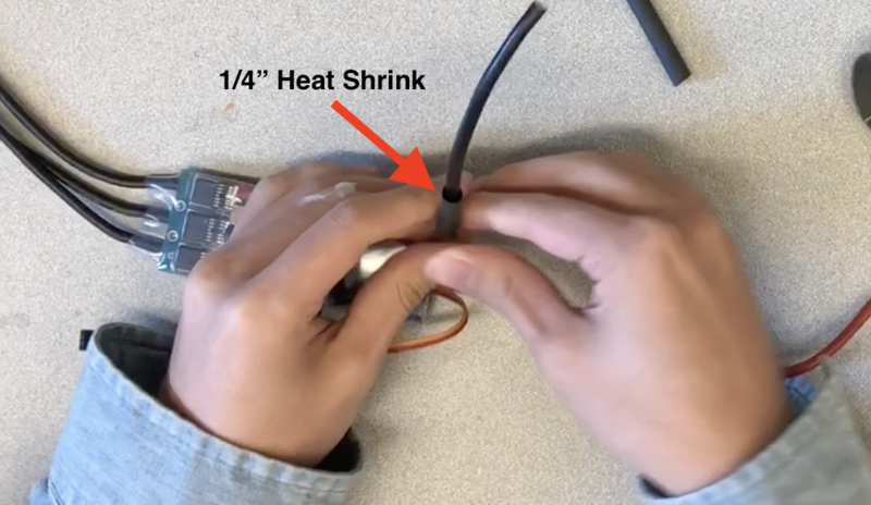
Fig. 1.1
For each stripped wire, twist the wire strands into a tight bunch such that they can fit inside of the solderless wire connectors. (Fig. 1.2)
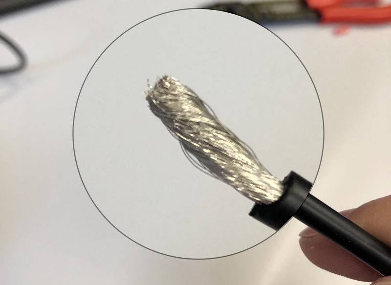
Fig. 1.2
Insert the stripped end of one of the battery connector’s wires into the solderless wire connector. The exposed copper should be inside of the metallic cylinder of the solderless wire connector. Ensure that no exposed copper is sticking out of the solderless wire connector. (Fig. 1.3)
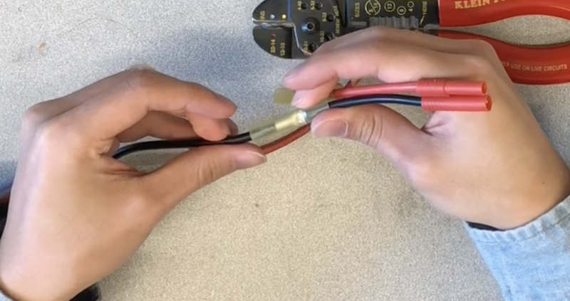
Fig. 1.3
Use the crimping tool to crimp the solderless wire connector onto the battery connector’s exposed copper. Ensure that the crimp is tight and complete by holding onto the solderless wire connector and tugging on the crimped wire. If tugging causes the connection to slip or disconnect, go back to step 5. (Fig 1.4)
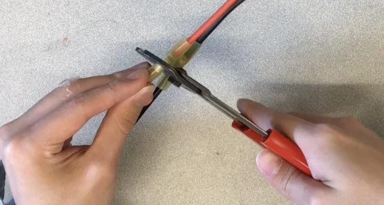
Fig. 1.4
Insert the stripped end of the VESC’s corresponding battery wire (i.e. the one that has the same color as the battery connector from the previous step) into the uncrimped end of the solderless wire connector. Repeat step 4 as necessary. Again, ensure that the exposed copper is inside of the solderless battery connector’s metallic cylinder, but that no exposed copper is sticking out of the solderless wire connector.
Repeat the process described in step 7 for the VESC’s inserted battery wire (instead of the battery connector wire).
Perform a final check of the strength of the connection by stiffly tugging on both of the crimped wires.
Use the heat gun to uniformly heat the solderless wire connector until it has completely shrunk. Be careful not to apply excessive heat.
Once the solderless wire connector has cooled down, adjust the 1/4" heat shrink so that it completely covers the solderless wire connector.(Fig. 1.5)
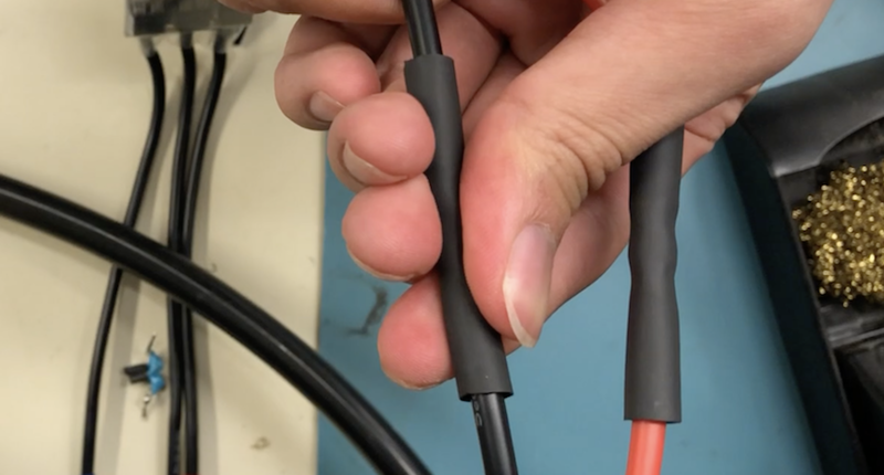
Fig. 1.5
Use the heat gun to uniformly heat the heat shrink until it has completely shrunk. (Fig. 1.6)
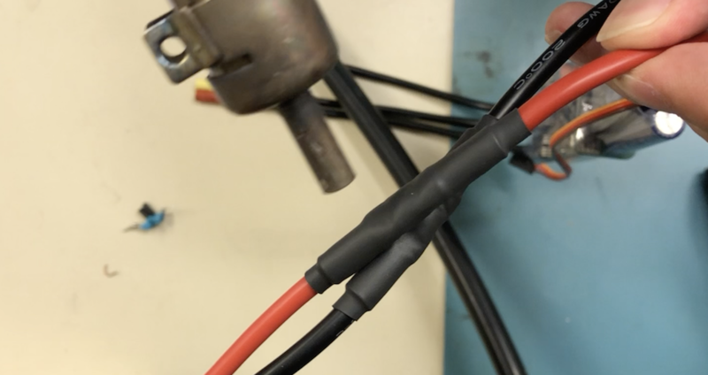
Fig. 1.6
This completes the connection of one of the battery wires. Repeat steps 6 through 13 for the other wire. (Fig. 1.7)
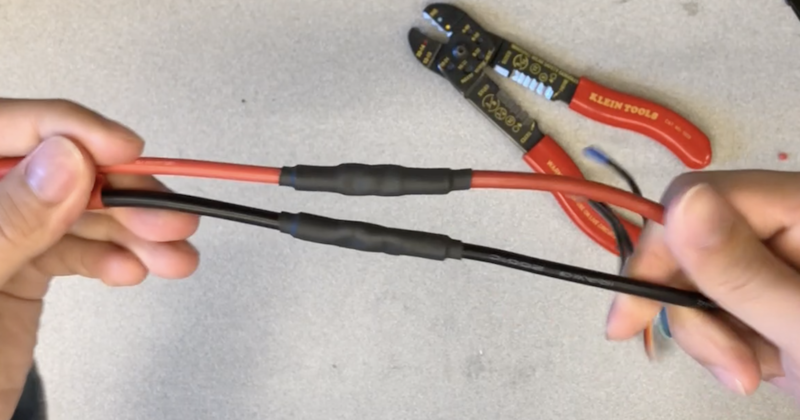
Fig. 1.7
Plug the USB mini cable into the VESC, and then plug the other end into a laptop or desktop.
We will now upload firmware to the VESC. First, plug the 3000 mAH battery into the VESC. Note that you should charge the battery if not done already.
Download the source code for bldc-tool
Install VESC Tool on the laptop or desktop. You will need to create an account and then download the free version of VESC Tool
Open VESC Tool, and then read through the VESC Tool Introduction dialog. Click Yes in the modemmanager dialog, as well as in the subsequent udev related dialogs. Then click the AutoConnect button located in the lowest third of the GUI in order to connect to the VESC. Click OK to dismiss the dialogs that pop up. Note that the lower right corner of the GUI should now display that the VESC is connected in limited mode. (Fig. 1.8)
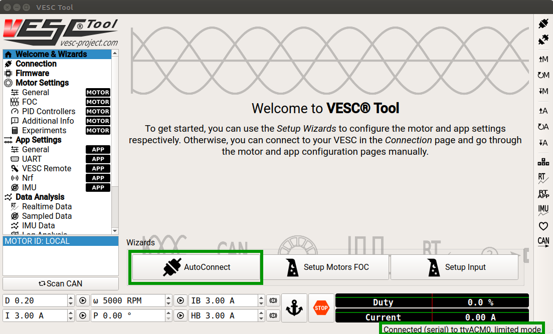
Fig. 1.8
Click on the Firmware tab in the left column of the GUI. Then click the Custom File tab near the top of the GUI. Click on the folder icon and choose the file located at bldc-tool/firmwares/hw_410_411_412/VESC_servoout.bin. Note that it is VERY important to choose the correct file. After verifying that you have chosen the correct file, click the downwards arrow icon to upload the firmware. Read the warning and click Yes to continue uploading firmware. (Fig. 1.9)
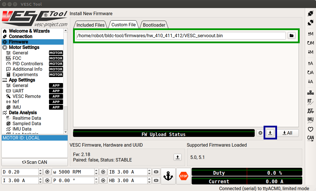
Fig. 1.9
Click OK to dismiss the post-firmware upload dialog. Wait one minute before continuing to ensure that the VESC has completed any firmware update related actions. Then close VESC Tool. Unplug the USB cable from the laptop or desktop, and unplug the battery from the VESC.
Servo Motor Removal
In this section, we will describe the steps necessary to remove the stock servo motor from the chassis. In a later section, we will install a more powerful servo motor.
Required Materials and Tools
- Hex Keys
- Racecar Chasis
- Philips Screwdriver
- Pliers
Steps
Flip the car over and remove the five screws that are holding the motor in place. (Fig. 2.1)
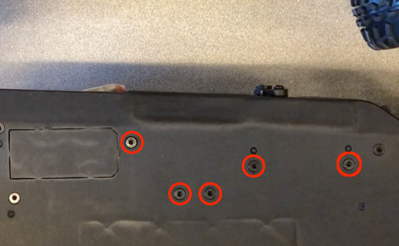
Fig. 2.1
Flip the chassis back over and take out the servo motor mount. It is still connected to the brushed motor, which will be removed in the next section.
A linkage connects the servo arm to the chassis. Use pliers to disconnect this linkage from the chassis. (Fig. 2.2)
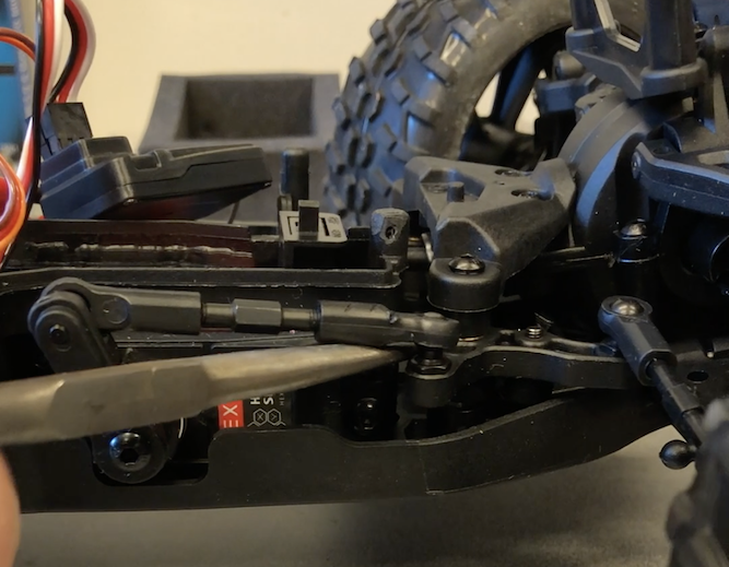
Fig. 2.2
Unscrew the servo motor arm from the servo motor. Remove the linkage from the servo arm. (Fig. 2.3)
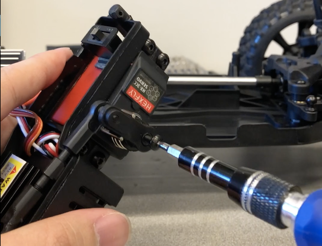
Fig. 2.3
Keep the metal linkage, as it will be used later when we install a more powerful servo motor.
Brushed Motor Removal
In this section, we will remove the brushed motor that comes with the chassis. Removing the brushed motor and replacing it with a BLDC motor (as detailed in the following section) requires a significant amount of time and effort. An alternative is to instead buy the Pro Version of the Redcat Blackout racecar chassis. This will lead to a slightly more expensive build, but that chassis already has a BLDC motor installed.
Required Materials and Tools
- Racecar Chasis
- Hex Keys
- Philips Screwdriver
- Pliers
Steps
Use the screw driver to remove the front and back cover mounts. (Fig. 3.1)
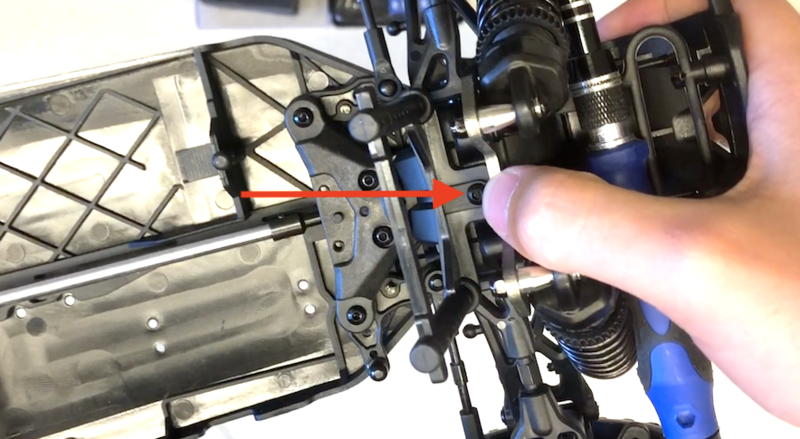
Fig. 3.1
A metal bar holds the upper suspension between the chassis and right rear wheel in place. This metal bar is in turn held in place by a screw. This screw is highlighted in Fig 3.2 below, remove it.
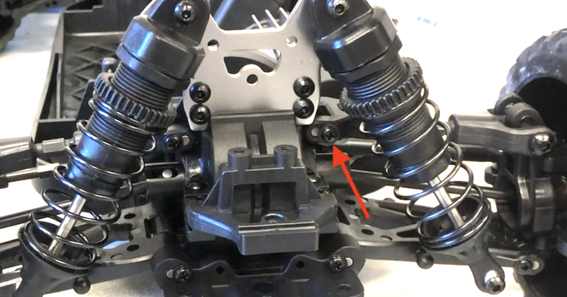
Fig. 3.2
Remove the metal bar that is holding the upper suspension in place by wiggling the upper suspension back and forth. Apply downwards pressure onto the upper suspension while wiggling it back and forth. This method is a bit tricky, and requires a little bit of patience. Alternatively, the metal bar can be pushed out by inserting a small object into the front of the bar’s cavity. Once a few millimeters of the metal bar has been wiggled/pushed out, use pliers to fully pull it out while continuing to wiggle the upper suspension as necessary. (Fig. 3.3)
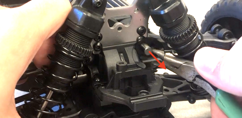
Fig. 3.3
Store the metal bar and screw, they will be re-installed later.
Two linkages connect the motor gear cover to the rear wheel mounts. Pry both of these linkages off of the motor gear cover with a screw driver or pliers. (Fig. 3.4)
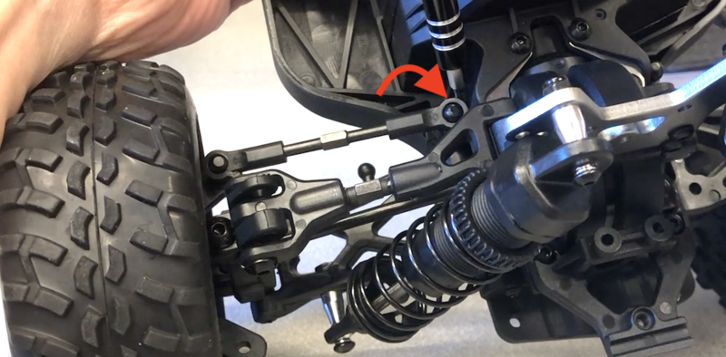
Fig. 3.4
Rotate the rear right wheel away from the chassis to release the wheel shaft. Store this shaft for later re-installation.
Flip the car over and remove the nine screws that attach the rear suspension, motor mount, and the motor gear cover to the chassis of the car. (Fig 3.5)
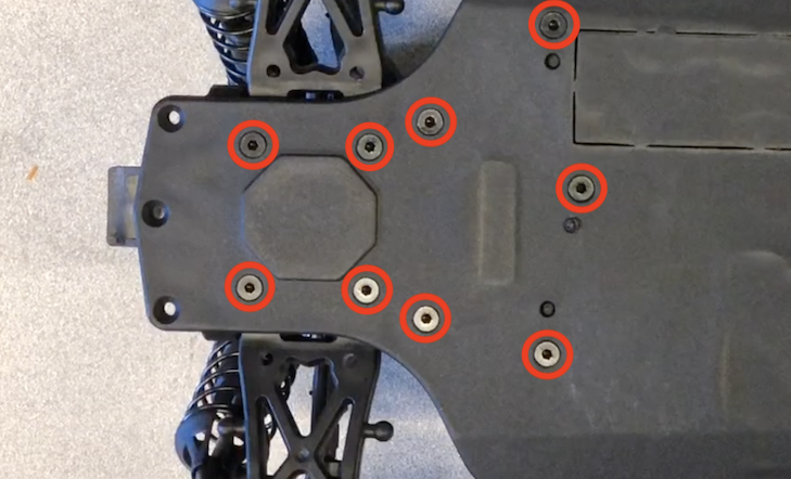
Fig. 3.5
Flip the car back over and remove the four screws on top of the motor gear cover. (Fig 3.6)
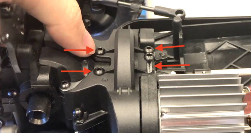
Fig. 3.6
Remove the motor gear cover.
Remove the two screws that secure the motor to its mount. (Fig. 3.7, Fig. 3.8) Be sure to orient the screwdriver as perpendicularly as possible with the face of the screw to avoid stripping the screw.
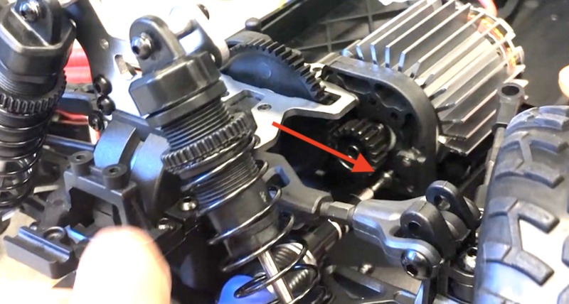
Fig. 3.7
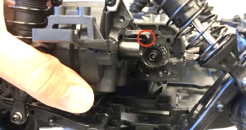
Fig. 3.8
To finally release the motor, we must remove the motor gear pinion. First, rotate the motor gear pinion so that the screw is facing towards the right side of the chassis such that it is aligned with the indent in the plastic motor mount. This indent allows for extra space when inserting a hex key.
Take extra caution in this step because the motor gear pinion screw is extremely tight and can easily be stripped, leaving the motor stuck. It may be helpful to apply heat to the motor gear pinion screw in order to dissolve the thread locker that has been applied. A soldering iron or heat gun can be used to apply heat. When unscrewing, make sure to check that the hex key tightly fits inside of the screw hole, and push the hex key into the screw hole with a large amount of pressure WHILE UNSCREWING to ensure that it does not slip out. If you feel the hex key starting to slip or strip, stop unscrewing and re-insert the hex key before trying again.
Using the above bolded guidelines, insert the hex key and remove the motor gear pinion screw. (Fig. 3.9)
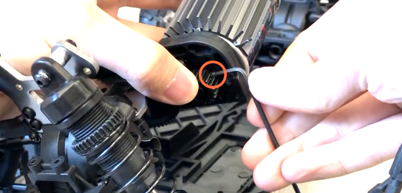
Fig. 3.9
With the motor gear pinion screw removed, slip the motor gear pinion off of the motor shaft and remove the brushed motor from the motor mount. The motor gear pinion and its screw will be reused when installing the BLDC motor.
Brushless Motor Installation
In this section, we will install the BLDC motor.
Required Materials and Tools:
- BLDC Motor
- Racecar Chasis
- Hex Keys
- Philips Screwdriver
- Pliers
Steps
Orient the motor so that the wires are above the motor casing.
Mount the motor to the chassis by inserting screws into the lower hole of the upper right pair and the upper hole of the lower left pair (Fig. 4.1). Use the same screws that previously held the brushed motor in place.
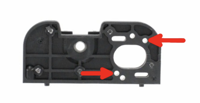
Fig. 4.1
Re-insert the drive shaft if it is no longer in position. (Fig. 4.2)
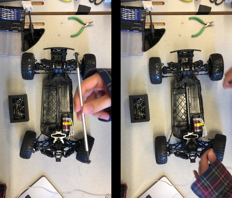
Fig. 4.2
Flip the car onto its side and re-insert the three screws that fasten the motor mount to the chasis. This ensures that the drive shaft will stay in place.
Note that the motor shaft is not entirely round, there is a flat edge. Locate that flat edge, and use pliers to rotate the shaft so that the flat edge is facing towards the right side of the chassis.
Re-install the motor gear pinion so that the screw hole of the motor gear pinion is aligned with the flat side of the motor shaft. Thus, once the screw is reinserted (don’t do it yet), the end of the screw will be in contact with the flat edge of the motor shaft, preventing the motor gear pinion from slipping. Also, ensure that the motor gear pinion is pushed as far back onto the shaft as possible while at the same time being able to be screwed in from the right side. (Fig 4.3)
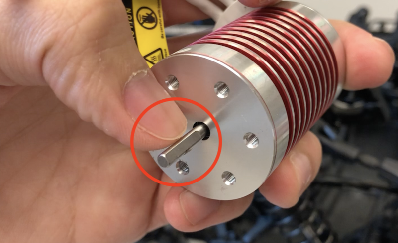
Fig. 4.3
Insert the motor gear pinion screw. Tighten the screw as much as possible, but be careful not to strip it.
Lift the car and spin the drive shaft gear to test that the drive shaft and motor gears have properly mated. The motor gear should turn as you spin the drive shaft gear without much resistance.
Re-insert the right rear wheel shaft and rotate the rear wheel towards the chassis to hold it in place.
Place the upper suspension back to its original position, and secure it in place by re-inserting the metal rod. Use pliers to re-insert the rod if necessary.
Re-install the screw that originally held the metal rod in place. (Fig. 4.4)
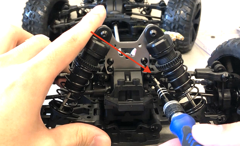
Fig. 4.4
Re-install the plastic motor gear cover into its original position.
Re-attach the two rear linkages to the motor gear cover by pushing their unconnected ends back down onto the metal balls. Use pliers if necessary.
Flip the car over and re-insert all of the screws that attach the rear suspension to the car chassis. (Fig. 4.5)
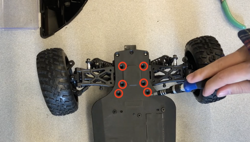
Fig. 4.5
Flip the car back over, place it on the floor, and lightly push it forward. The car should freely move forward at least a few feet before coasting to a stop. Then repeat, except push it backwards. If the car doesn’t freely move forward/backward, the motor gear pinion is most likely not pushed in far enough and is rubbing against the motor gear cover. Go back to step 6 if this is the case.
Insert the four top screws into the motor gear cover to secure it. (Fig. 4.6)
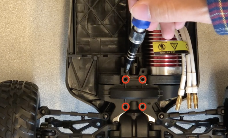
Fig. 4.6
Again verify that the car moves freely when pushed (as described in step 15). If it does, the brushless motor has been successfully installed.
Servo Motor Installation
In this section, we will install a servo motor into the racecar chassis. Compared to the stock servo motor, the replacement servo motor is much more powerful. This allows the racecar to effectively steer, despite the additional weight that will be mounted to the chassis in later sections.
Required Materials and Tools
- Racecar Chasis
- 3D Printed Parts
- Servo Cage
- 6x M2.5 Hex Nuts
- 2x M2.5 Flat Head Screws
- 4x M2.5 Pan Head Screws
- 20 KG servo motor
- Threadlocker
- Hex Keys
- Philips Screwdriver
- Pliers
Steps
Insert six hex nuts into the inlets below each of the servo cage’s screw holes. (Fig. 5.1)
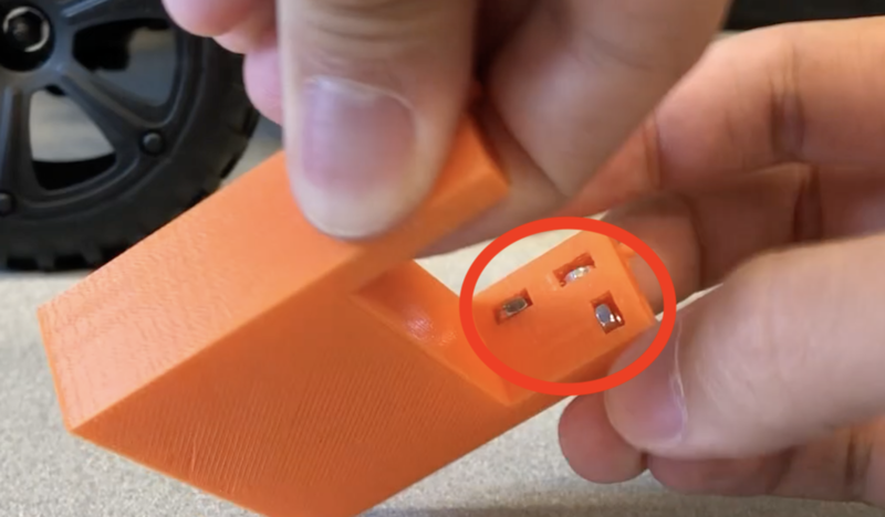
Fig. 5.1
Take out the servo motor, but do not attach the metal arm yet. Orient the servo motor into the servo cage such that the motor gear is on the same side as the four screw holes, and the motor wire is oriented towards the knotch in the back of the servo cage. The servo motor should prevent the six hex nuts from falling out of their holes. (Fig. 5.2)
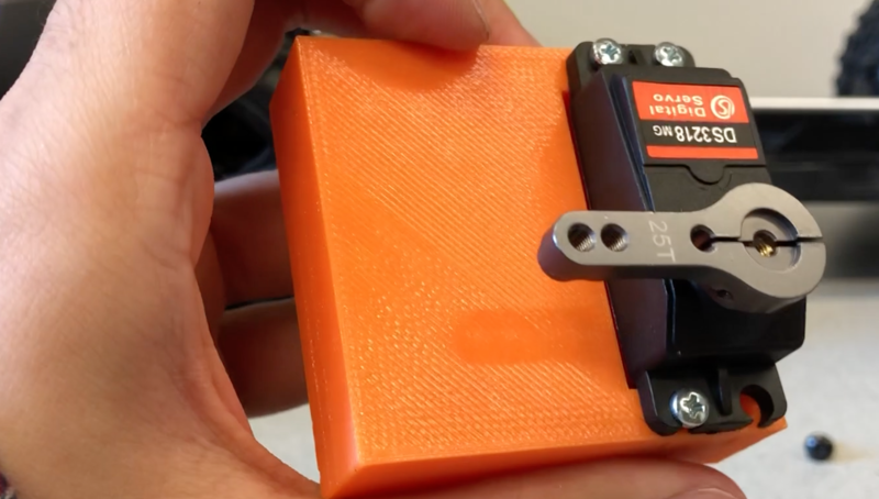
Fig. 5.2
Insert four M2.5 pan head screws to mount the servo motor to the servo cage.
Attach the metal servo arm onto the servo motor so that it points directly upwards. (Fig. 5.3)
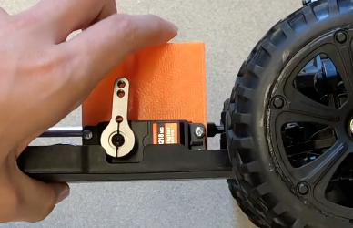
Fig. 5.3
Use the screw that came with the servo motor to secure the servo arm to the servo motor.
Position the servo motor cage on the chassis. Orient it so that the servo arm is facing towards the right side of the race car and the wires run towards the back of the car. The two stubs on the servo motor cage should protrude through the corresponding holes of the chassis. (Fig. 5.4)
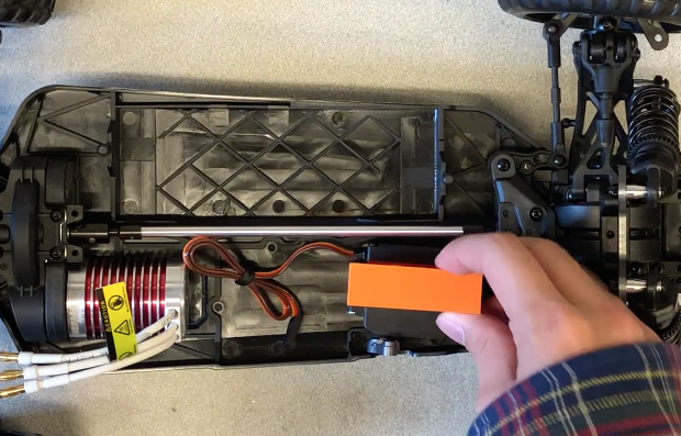
Fig. 5.4
Flip the car over and attach the servo cage to the chassis with two M2.5 flat head screws.
Note the metal ball screwed into the old/stock servo arm. Unscrew it with the pliers.
Apply threadlocker to the threads of the metal ball. Then screw the ball into the lower hole of the new servo arm. Tighten it by screwing it with the pliers.
Re-attach the servo linkage that was removed from the old servo motor. First re-attach it to the chassis by pushing it down onto the chassis’ metal ball.
Line up the linkage with the servo arm’s metal ball by turning the wheels and/or the servo arm, and then attach it with pliers. (Fig. 5.5)
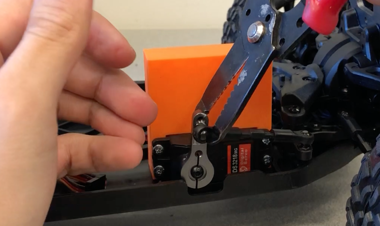
Fig. 5.5
Test that manually panning the wheels causes the servo arm to move forwards and backwards. If it does, the servo motor has been installed successfully.
Lower Platform Installation
In this section, we will install the car’s lower platform, which will serve as a foundation for mounting additional electronics. This involves attaching the VESC to the bottom of the foundation, mounting the foundation onto the racecar chassis, and affixing the buck converter to the top of the foundation.
Required Materials and Tools
- 3D Printed Parts:
- Back Foundation
- Front Foundation
- Lower Left Foundation Support
- Lower Right Foundation Support
- Upper Left Foundation Support
- Crossbar Upper Support
- Crossbar Buttom Support
- Racecar Chasis
- VESC
- Buck Converter
- 3 Pin Through Hole Male Header
- Electrical Tape
- 4 x M3 Flathead Screws (40mm)
- 27x M2.5 Hex nuts
- 10x M2.5 Flat Head Screws
- 4x M2.5 Pan Head Screws
- 4x Nylon Spacers
- Zip Ties
- 3000 mAH NiMH Battery (7.2 V)
- Super Glue
- Hex Keys
- Philips Screwdriver
Steps
Put the 3000 mAH NiMH battery into the battery compartment on the left side of the racecar chassis. Orient the battery such that the wires run towards the front of the racecar chassis.
Use two M2.5 flat head screws and nuts to attach the two tabs extending out the back of the front foundation to the corresponding holes near the front of the back foundation.
Note the two holes in the middle of the metal crossbar that came with the racecar chassis. Align them with the two holes in the middle of the now unified foundation (the metal crossbar should be below the foundation), and then attach the metal crossbar to the foundation with two M2.5 flathead screws and nuts. (Fig. 6.1)
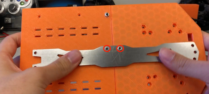
Fig. 6.1
Turn the foundation over so that the metal crossbar is on top. If using the DZS Elec LM2596 buck converter, insert four M2.5 hex nuts into the holes outlined in red in Fig. 6.2. If using the DROK 180051US buck converter, insert four M2.5 hex nuts into the holes outlined in blue in Fig. 6.2. Add super glue into the spaces between the edge of the hole and the hex nuts in order to keep the hex nuts in place. Be careful not to get super glue into the threads of the hex nuts. Allow the super glue to dry before continuing. (Fig. 6.2)
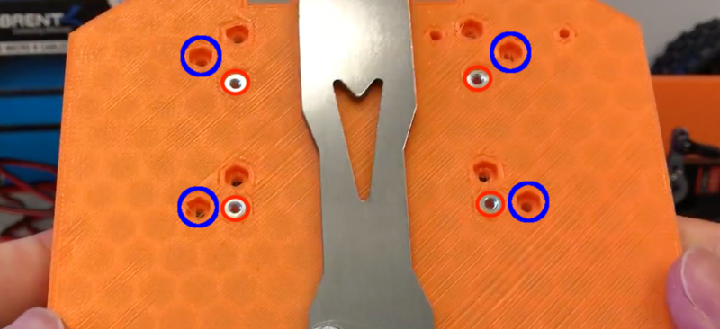
Fig. 6.2
Insert two M2.5 hex nuts into the inlets below the screw holes of the lower right foundation support. Align the lower right foundation support with the corresponding screw holes on the foundation, and then use two M2.5 flat head screws to secure it to the foundation. (Fig. 6.3)
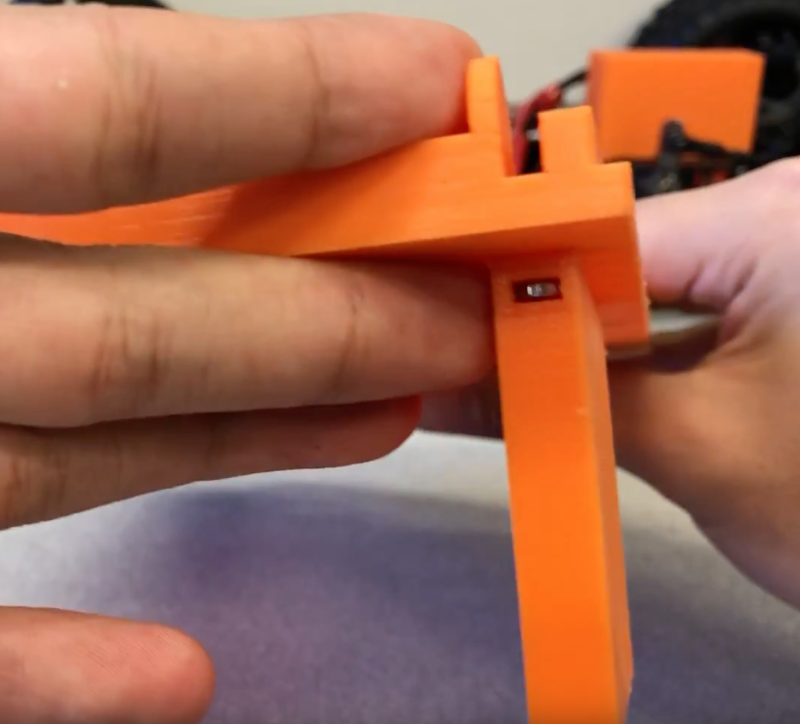
Fig. 6.3
Repeat step 5 for the lower left foundation support. (Fig 6.4)
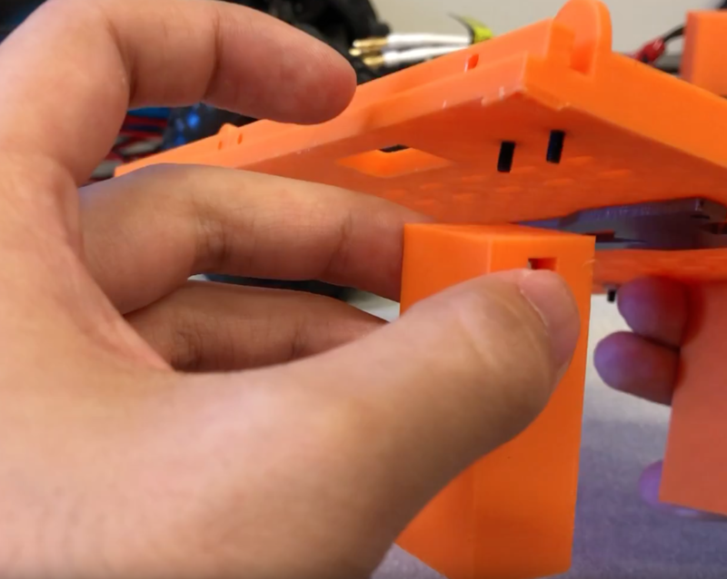
Fig. 6.4
Repeat step 5 for the upper left foundation support. (Fig 6.5)
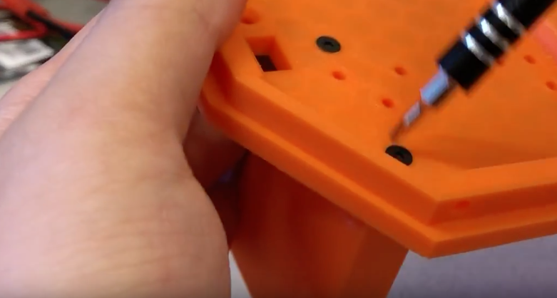
Fig. 6.5
Align the 3D printed lower crossbar support with the holes in the back of the metal crossbar, and insert two M3 40mm Flat Head screws down through the foundation. Repeat this for the 3D printed upper crossbar support and the front holes of the metal crossbar.
Now we will mount the VESC to the bottom of the foundation. Place it between the lower right foundation support and metal crossbar, such that it will be above the BLDC motor once the foundation has been mounted to chassis. Orient it such that the three BLDC motor connector wires run towards the back of the foundation, and the USB mini port faces towards the metal crossbar. (Fig. 6.6)
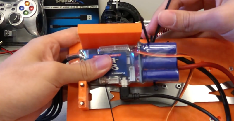
Fig. 6.6
Use zip ties slipped through the gaps in the foundation to mount the VESC to the foundation as shown in Fig. 6.7. Chain zip ties together if extra length is necessary. Make sure that the zip ties do not significantly protrude out from the top of the foundation.
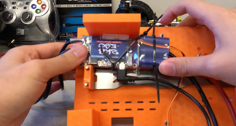
Fig. 6.7
Use zip ties to secure the VESC battery wires and USB mini cable to the bottom of the foundation. (Fig. 6.8)
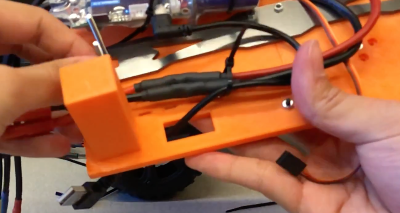
Fig. 6.8
Use pliers to remove the individual pins from the 3 pin male header. Use these pins to connect the three pin female header of the VESC to the three pin female header of the servo motor. Connect them such that corresponding colors are connected together (e.g. Red connects to red, black connects to black/brown).
Wrap electrical tape around the connection between the VESC and servo motor.
Organize the servo motor wire into a neat bundle with a zip tie.
Orient the foundation right-side-up and align it with the chassis. Connect the VESC’s motor wires to the BLDC motor. Assuming the VESC is positioned above the BLDC motor and oriented as described in step 9, each VESC wire should be connected to the BLDC motor in the corresponding position. That is, the furthest left VESC motor wire should be connected to the furthest left BLDC motor wire, the middle VESC wire should be connected to the middle BLDC motor wire, and the furthest right VESC wire should be connected to the furthest right BLDC motor wire. (Fig 6.9)
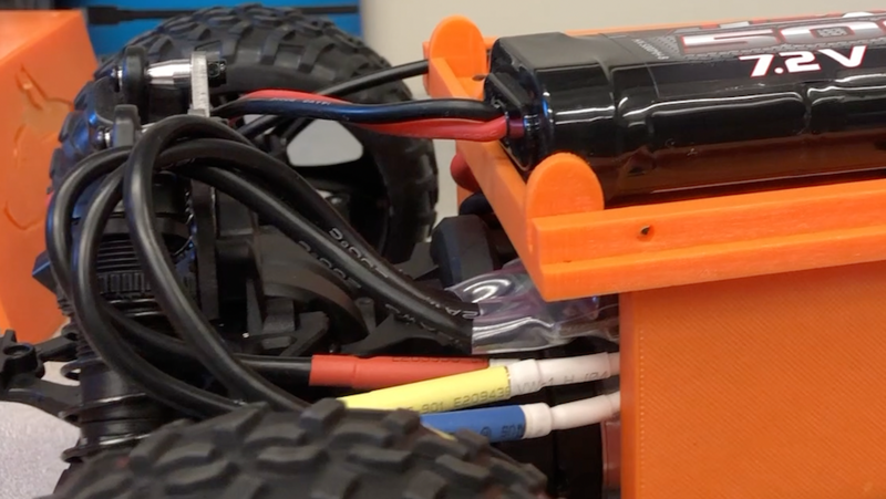
Fig. 6.9
Mount the foundation to the chassis by screwing in the four M3 40mm flathead screws that go through the crossbar supports to the race car chassis. This may be a tight fit due to the VESC, so push down on the foundation if necessary. Make sure that none of the supports get caught on the wall of the chassis and that none of the VESC’s wires get caught between the foundation and the servo cage. (Fig 6.10)
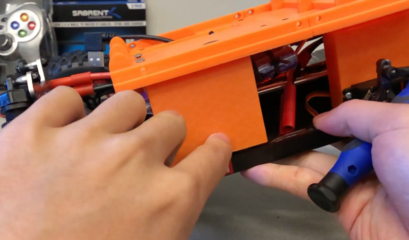
Fig. 6.10
Insert nine M2.5 hex nuts into the hex shaped holes along the inner surface of the foundation walls. Apply super glue in between the edges of each nut and the plastic, but be careful not to get super glue into the threads of the hex nuts.
Slip four M2.5 pan head screws through the mounting holes of the buck converter. Then slip a nylon spacer onto each of the screw shafts. Then screw a M2.5 hex nut onto each of the screw shafts until it loosely holds the nylon spacer against the bottom surface of the buck converter. (Fig. 6.11)
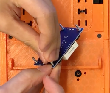
Fig. 6.11
Insert the buck converter’s mounting screws into the corresponding mounting holes of the foundation. (Fig. 6.12)
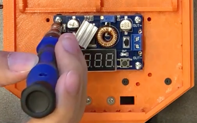
Fig. 6.12
Buck Converter Configuration
In this section, we will configure the buck converter. The buck converter steps down the battery voltage (~7-8 V) to the voltage required by the Jetson Nano (5.0 V). Thus, we must perpare two connections: one between the battery and buck converter, and one between the buck converter and Jetson Nano. We will also adjust the buck converter’s potentionmeter to achieve the correct output voltage.
Required Materials and Tools
- Barrel Connector 5.5x2.1 mm
- 2x Solderless Wire Connectors (Heat Shrink Butt Connector)
- 1/4" Heat Shrink
- Battery Connector
- 5000 mAH NiMH Battery
- Hot Glue Gun
- Heat Gun
- Crimping Tool
- Wire Stripper/Cutter
- Flathead Screwdriver
Steps
Buck Converter to Jetson Nano Connection
Cut the barrel connector’s wires to a length of approximately 30 cm. Keep the extra wire as we will reuse it later.
Strip approximately 7.5 mm of insulation off of the ends of the wires.
Use a flathead screwdriver to unscrew the output terminals of the buck converter. This allows the exposed ends of the barrel connector’s wire to be slipped into the output terminals. The red wire should go into the terminal marked OUT+, and the black wire should go into the terminal marked OUT-. Push them in far enough such that no exposed copper hangs out of the output terminals (use wire cutters to shorten the exposed ends if necessary). (Fig. 7.1)
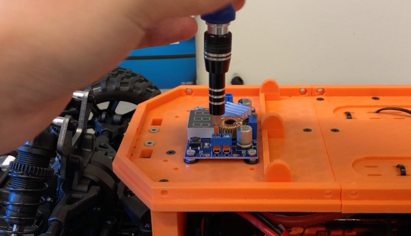
Fig. 7.1
While holding the wires in place, tighten the output terminal screws to secure the wires in place. Gently tug on the wires to check that they will not slip out of the output terminals. Again check that no exposed copper hangs out of the output terminal, and that there are no shorts between the two wires. (Fig. 7.2)
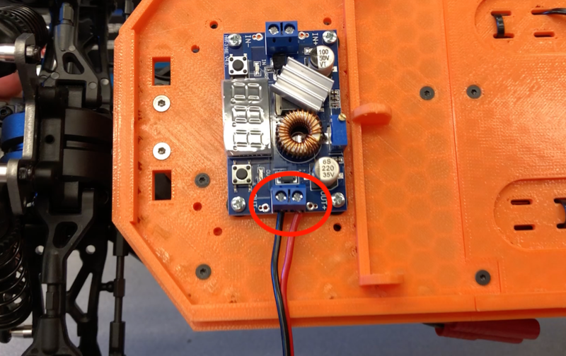
Fig. 7.2
Cover the wire insertion point and surrounding area in hot glue. This strengthens the connection and will further prevent short circuits between the two wires. (Fig. 7.3)
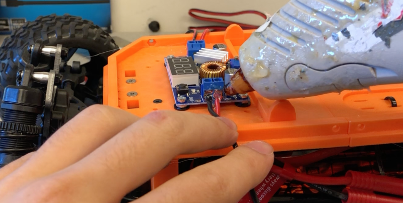
Fig. 7.3
Battery to Buck Converter Connection.
Cut a length of wire of approximately 22 cm. Create this length of wire from the extra wire that was cut off of the barrel connector in step 1.
Using two solderless wire connectors and heat shrink, connect the 22cm length of wire to the battery connector. Use the exact same process that was detailed in the VESC Preparation section, particularly steps 2-13.
Install the other end of the 22 cm length of wire into the input terminals of the buck converter. The process is exactly the same as steps 2-5 in the previous subsection, except that the red wire should go into the terminal marked IN+, and the black wire should go into the terminal marked IN-.
The connections for the input and output of the buck converter are now complete, as shown in Fig 7.4.
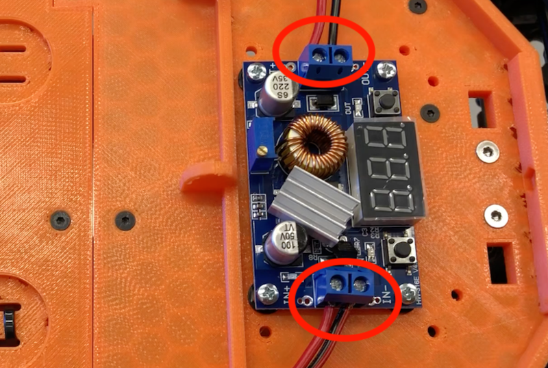
Fig. 7.4
Buck Converter Voltage Adjustment
The following instructions detail voltage adjustment for the DZS Elec LM2596 buck converter. If you are using a different buck converter, follow the manufacturer’s instructions to set the output voltage to 5.2V.
Before continuing, make sure that the barrel connector is NOT plugged into the Jetson Nano.
Place the 5000 mAH battery in the lower foundation’s right battery compartment, and plug it into the buck converter. The buck converter’s LED screen should light up and display numbers.
Press the button labeled OUT on the buck converter.
Use a flat head screw driver to adjust the potentiometer until the LED screen displays 5.2, which indicates that the buck converter is outputting 5.2V. Note that we set the voltage to 5.2V rather than 5V because we have observed that current drawn from the buck converter by the Jetson causes the voltage to drop slightly.
Unplug the battery from the buck converter.
Place hot glue over the potentiometer to prevent any inadvertant adjustment of the potentiometer in the future. (Fig. 7.5)
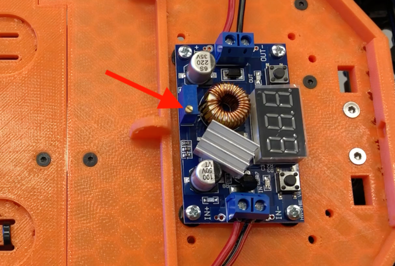
Fig. 7.5
Expose the adhesive backing of the heat sink that came with the buck converter and attach it to the IC shown in Fig. 7.6.
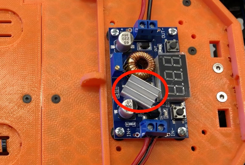
Fig. 7.6
Push Button Installation
In this section, we will mount the push button to the chassis’ front bumper.
Required Materials and Tools
- Racecar Chassis
- Push Button
- 4x Female to Female Jumper Cable
- 1K Ohm Resistor
- 1/8” Heat Shrink
- 2x 20mm M2.5 Pan Head Screws
- 2x M2.5 Hex Nuts
- 4x Nylon Spacers
- Electrical Tape
- Screw Driver
- Heat Gun
- Wire Cutters/Strippers
Slip a nylon spacer onto each of the two 20mm M2.5 Pan Head Screws, and then insert the screws through the mounting slots of the push button.
Align the mounting slots of the push button with the slots on the front bumper. (Fig. 8.1)
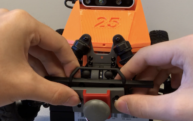
Fig. 8.1
Slip another nylon spacer onto each of the screw shafts so that they are pressed up against the back surface of the front bumper.
Secure the push button onto the front bumper by installing nuts onto the screw shafts. (Fig. 8.2)
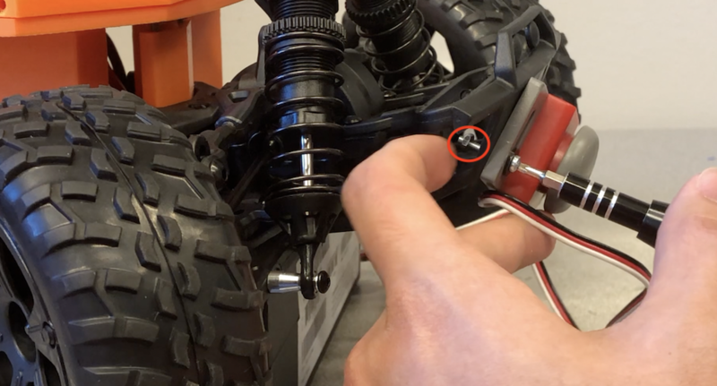
Fig. 8.2
Slip the push button’s wires underneath the chassis’ lower suspension, and then up through one of the holes in the front foundation. (Fig. 8.3)
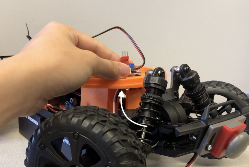
Fig. 8.3
Use the wire cutters to remove one of the female housings three of the jumper cables. Strip approximately one centimeter of insulation off of each of the cut ends. We will assign a letter to each jumper cable, so we have jumper cable A, jumper cable B, and jumper cable C. We will refer to the remaining, uncut jumper cable as jumper cable D.
Trim both of the resistor’s legs to be approximately 1cm long.
Take jumper cables A and B and tightly twist their exposed copper around one of the legs of the resistor. (Fig. 8.4)
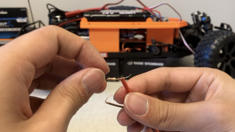
Fig. 8.4
Cut an approximately 5cm piece of 1/8" heat shrink and slip it onto jumper cable C.
Tightly twist the exposed copper of jumper cable C around the unconnected leg of the resistor. (Fig. 8.5)
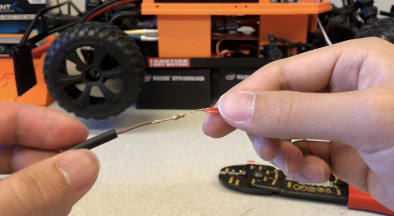
Fig. 8.5
Slip the heat shrink over the resistor so that it covers all exposed metal. Use a heat gun to uniformaly shrink the heat shrink. (Fig. 8.6)
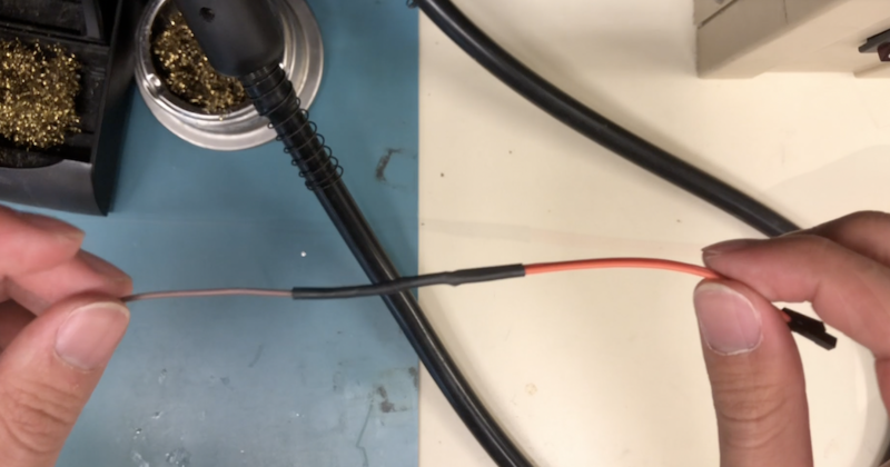
Fig. 8.6
Connect jumper cable A to the push button’s white wire, and jumper cable D to the push button’s black wire. Wrap electrical tape around the connection. In a later section, we will finish connecting the push button to the Jetson Nano.
YDLIDAR Installation
In this section, we will mount the YDLIDAR to the top of the racecar’s back cover.
Required Materials and Tools
- 3D Printed Parts
- Back Cover Top
- YDLIDAR
- USB Micro Splitter
- 4x M2.5 Pan Head Screws
- 8x M2.5 Hex Nuts
- 4x Nylon Spacers
- Hex Keys
- Philips Screw Driver
Steps
Orient the 3D printed back cover top (BCT) so that the side with exactly eight round holes faces upwards.
A separate printed circuit board (PCB) comes with the YDLIDAR. Insert four M2.5 pan head screws through its mounting holes. Then slip a nylon spacer onto each of the screw shafts. Then slip a M2.5 hex nut onto each shaft. The nut should loosely hold the nylon spacer against the bottom surface of the PCB.
Align the PCB’s mounting screws with the set of four holes on the BCT that are closest together. Orient the board so that the USB ports are facing towards the rectangular hole. Secure the screws in place with four M2.5 nuts inserted through the bottom of the BCT. (Fig. 9.1, 9.2)
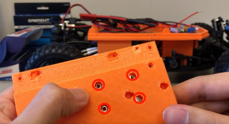
Fig. 9.1
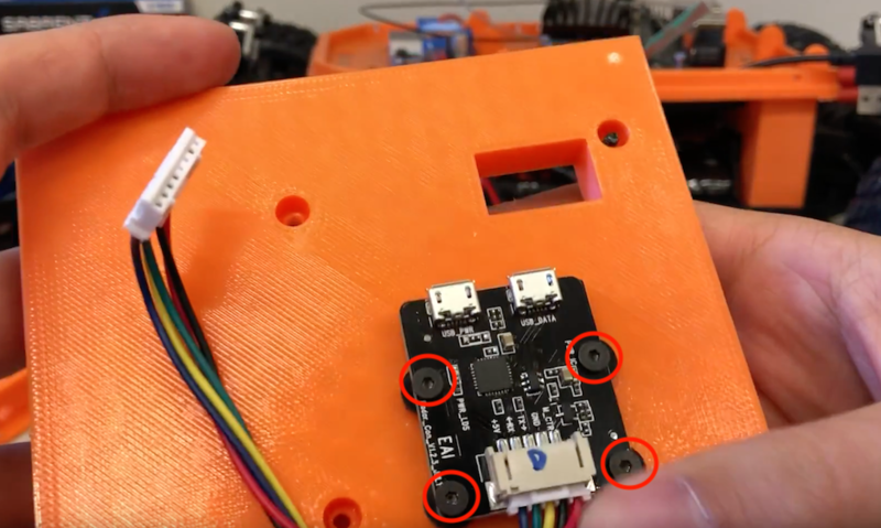
Fig. 9.2
Insert the legs of the YDLIDAR into the holes on top of the BCT. Secure them in place by inserting the four screws into the corresponding holes of the bottom of the BCT. Use the fours screws that came with the YDLIDAR.
Connect the YDLIDAR to the PCB with the provided set of wires. Also, plug the USB micro splitter into the PCB. Note the red plastic around one of the USB micro splits. This corresponds to power, which should be plugged into the USB connector labeled PWR on the PCB. Put the other USB micro split into the other USB connector of the PCB. Guide the USB Type A end through the rectangular hole of the BST.
The YDLIDAR is now successfully mounted, as shown in Fig. 9.3.
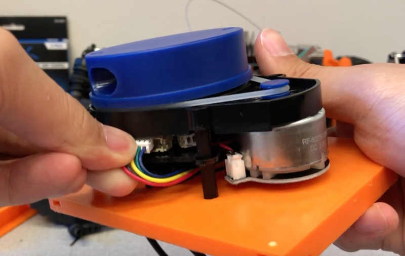
Fig. 9.3
Jetson Nano Wi-Fi Card Installation
In this section, we will install a Wi-Fi card and antennas into the Jetson Nano.
Required Materials and Tools
- Jetson Nano
- Wi-Fi Card
- 2x Wi-Fi Antenna
- Philips Screw Driver
Steps
Connect the Wi-Fi antennae to the Wi-Fi card. To do this, first place the card on a flat surface. To connect an antenna, align the neck of its connector to be perpendicular to the back edge of the card. Tilt the antenna connector so that only the back part is making contact with the connector on the card as shown in Fig 10.1. Place your thumb on top, and then apply firm pressure as you roll your thumb forward along the antenna connector. It should snap into place. It is a tight fit and can be difficult to make the connection, but do not force it as the connectors can break. (Fig. 10.1)
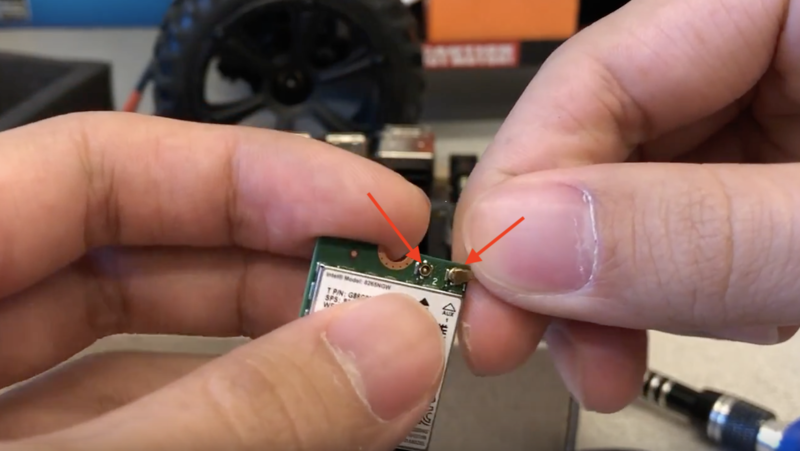
Fig. 10.1
Take out the two screws that secure the Jetson module to the carrier board. (Fig. 10.2)
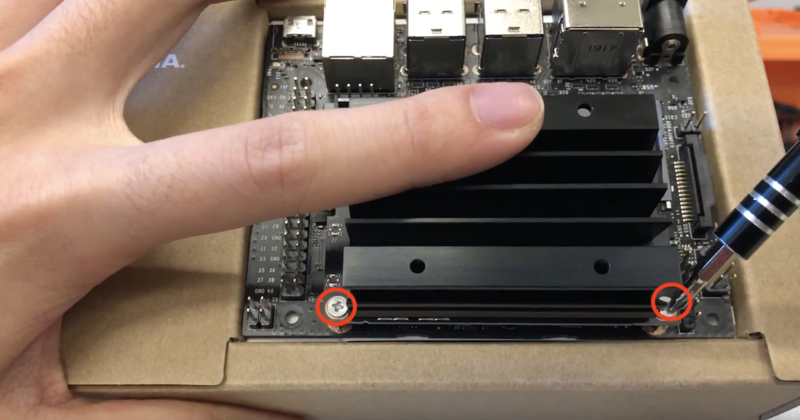
Fig. 10.2
Release the side latches that are on both sides of the module. These latches hold the module in place, and once released the module will pop up. Gently pull on the Jetson module to remove it. (Fig. 10.3)
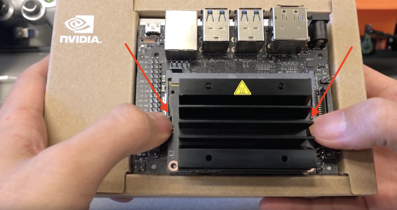
Fig. 10.3
Remove the #2 screw located in the center of the board.
Position the Wi-Fi card at a slight angle and insert it into the M.2 connector.
Re-insert the #2 screw to secure the Wi-Fi card in place.
Route the antennae wires such that they lay between the two Jetson module screw mounts. (Fig. 10.4)
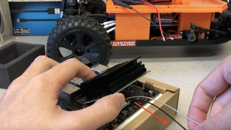
Fig. 10.4
Position the Jetson Nano module at a slight angle before re-inserting it into the carrier board socket. Push it back down so that it is retained by the latches.
Re-insert the screws to secure the Jetson module.
The Wi-Fi card is now successfully installed into the Jetson Nano.
SD Card Setup
In this section, we will write a system image with pre-installed MuSHR software to an SD card, and then insert that SD card into the Jetson Nano. If you use an SD card that has less than 128 GB of storage (or encounter other problems with this system image) you can install NVIDIA’s stock image and then use a script to install the necessary drivers by following the instructions here.
Required Materials and Tools
- Jetson Nano
- SD Card - (128GB or larger)
- Computer with
- Internet Connection
- Ability to Read and Write SD Cards (SD Card USB Adapter)
Steps
Download and decompress the MuSHR system image from here.
Flash the MuSHR image onto the SD card following the instructions here.
- username:
robot - password:
prl_robot
- username:
Insert the SD card into the Jetson Nano’s SD card slot.
Back Cover Installation
In this section, we will assemble the back cover, mount the Jetson Nano, and attach the back cover to the foundation.
Required Materials and Tools
- Jetson Nano
- 3D Printed Parts:
- Back Cover Top (w/ LIDAR mounted)
- Back Cover Left Side
- Back Cover Right Side
- Racecar Chasis
- 12x M2.5 Hex Nuts
- 8x M2.5 Pan Head Screws
- 4x M2.5 Flat Head Screws
- 12x Spacers
- Pin Jumper
- Hex Keys
- Tweezers
- Pliers
- Philips Screwdriver
- Electrical Tape
Steps
Before continuing, the LIDAR should already be mounted to the 3D printed back cover top (BCT).
Insert a M2.5 pan head screw into each of the Jetson Nano’s mounting holes. Then place two spacers on each screw shaft, followed by a M2.5 hex nut. Screw the nut onto the shaft such that it loosely holds the upper spacer against the bottom surface of the Jetson Nano.
Insert a M2.5 hex nut into each of the four hex inlets on the sides of the BCT. (Fig. 12.1)
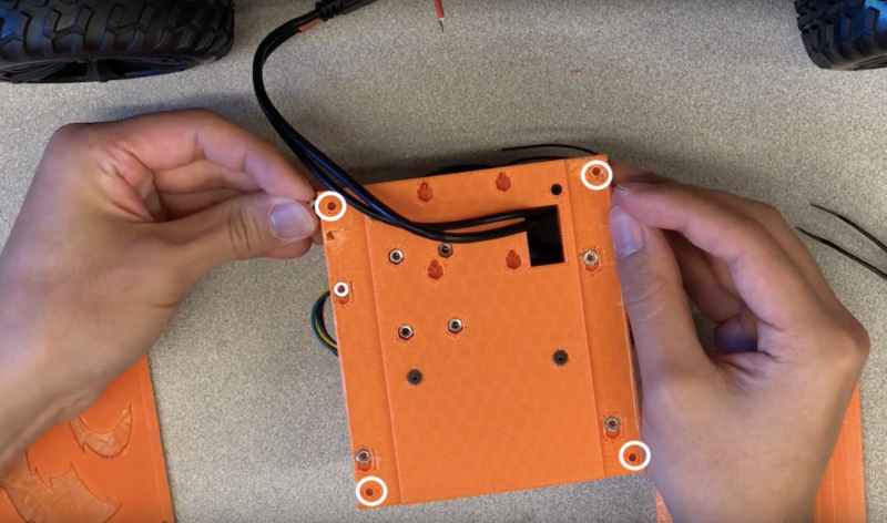
Fig. 12.1
Align the 3D printed back cover right side with the two holes on the right side of the BCT that are above the inlets from the previous step. Before inserting a M2.5 pan head screw into each of these holes, slip one nylon spacer onto the screw shaft.
Repeat the previous step with the 3D printed back cover left side in order to attach it to the BCT.
Observe the bottom surface of the BCT (i.e. the side opposite to the one the LIDAR is mounted on). Note the four mostly hexagonal holes near where the BCT connects to the back cover left side and back cover right side. Insert a M2.5 hex nut into each of these holes, and align their thread hole with the round portion of the hole. (Fig. 12.2)
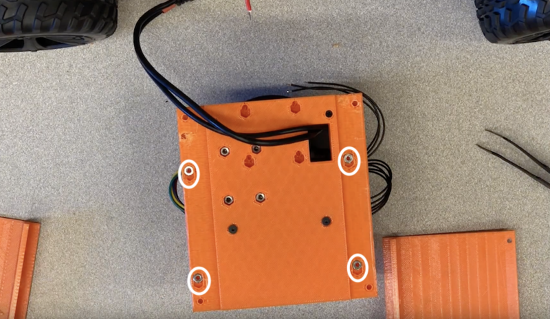
Fig. 12.2
Tilt the back cover so that the hex nuts from the previous step stay in place. Simultaneously align the Jetson Nano with these hex nuts, and secure its mounting screws to the BCT. (Fig. 12.3)
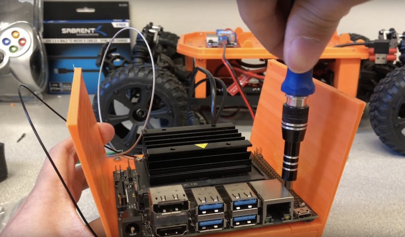
Fig. 12.3
Now that the Jetson Nano has been mounted, put a pin jumper on the J48 header, as shown in Fig 12.4, so that the Jetson Nano draws power from the DC barrel jack.
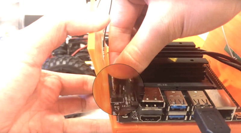
Fig. 12.4
Next, we will connect the push button to the Jetson Nano’s breakout pins. Note that in the following description, all pins refer to pins found on the Jetson Nano’s J41 header, and that we will refer to specific jumper cables as defined in the push button installation section. Connect jumper cable B to Pin 31, which serves as an input GPIO pin. Connect jumper cable C to Pin 1, which connects the pull-up resistor to 3.3V. Finally, connect jumper cable D to Pin 39, which serves as a ground connection when the button is pressed.
Optionally, apply hot glue to ensure that jumper cables B,C, and D do not become disconnected from their respective pins on the J41 header.
Expose the adhesive on the back of each of the antennas, and attach them to the side walls of the back cover.
Use electrical tape to re-enforce the adhesion of the antennae to the side walls.
If necessary, use zip ties to bundles the antennae wires, as well as perform general cable management of the back cover. (Fig. 12.5)
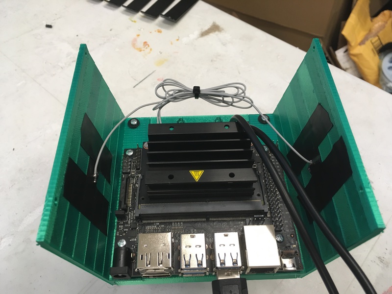
Fig. 12.5
Use four M2.5 flat head screws to mount the back cover to the foundation. (Fig. 12.6)
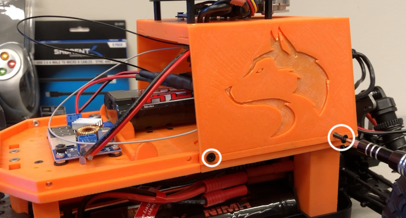
Fig. 12.6
Front Cover Installation
In this section, we will mount the D435i Realsense camera to the front cover of the car, and attach the front cover to the foundation.
Required Materials and Tools
- Intel D435i Camera and/or Intel T265 Camera
- USB 3.0 1ft Cable
- 3D Printed Parts:
- Racecar Front Cover Whole
- Racecar T265 Mounting Plate (If using 2 Cameras)
- Racecar Chasis
- 5x Flat Head Screws
- 2x 6mm M3 Pan Head Screws (If using 1 Camera)
- 4x 14mm M3 Pan Head Screws (If using 2 Cameras)
- 8x Nylon Spacers (If using 2 Cameras)
- Pliers
- Hex Keys
- Philips Screwdriver
Steps
Plug the 1ft USB 3.0 cable into the D435i camera. Note that we are not using the USB cable that comes with the camera because it is excessively long.
Single Camera Guide the USB cable from the outside of the front cover to the inside through the gap near the mounting holes. (Fig. 13.1)
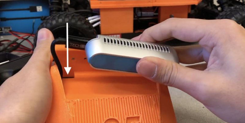
Fig. 13.1
Single Camera Use two 6mm M3 screws to mount the D435i camera to the front cover.(Fig. 13.2)
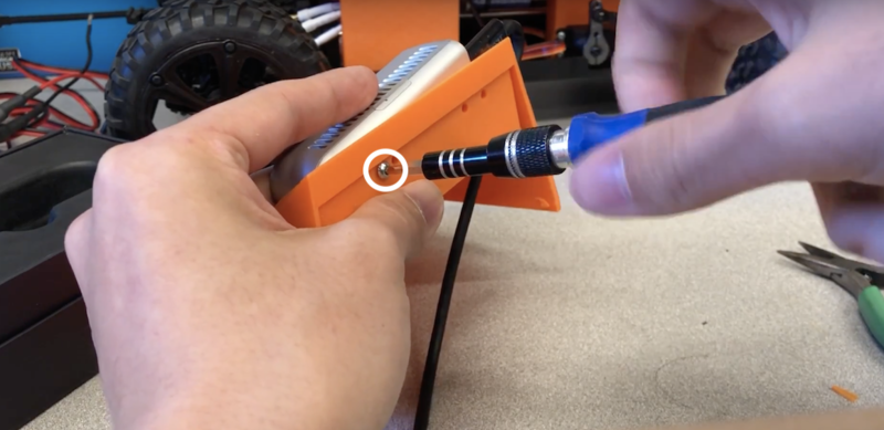
Fig. 13.2
Dual Camera Use two 14mm M3 screws to attach the mounting plate and D435i camera to the front cover. (Fig. 13.3)
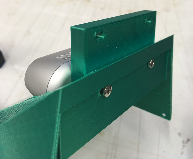
Fig. 13.3
Dual Camera Take two 14mm M3 screws and slip 4 nylon spacers onto each of them. Use these screws to attach the T265 camera to the mounting plate. (Fig. 13.4).
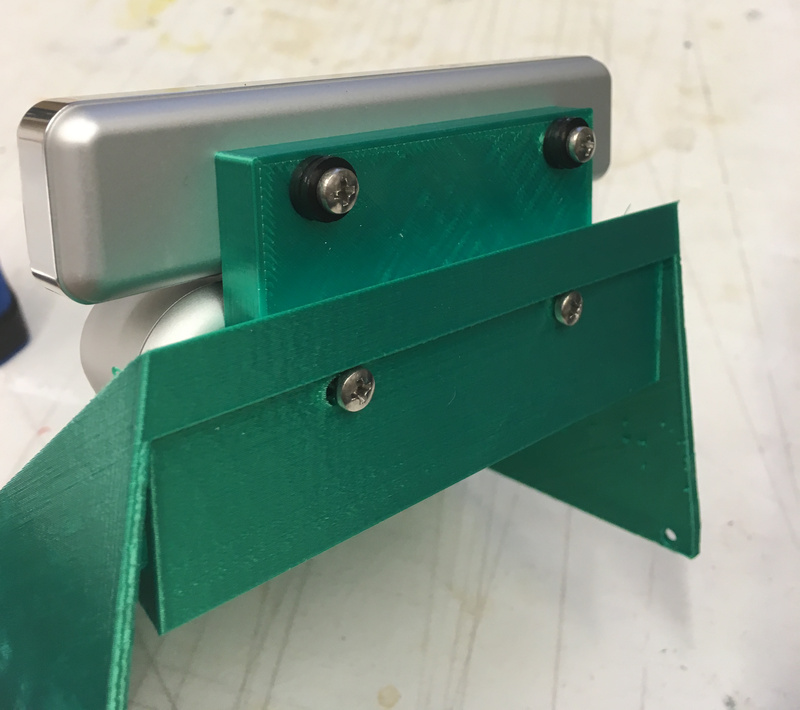
Fig. 13.4
Dual Camera Guide the USB cables from the inside of the front cover to the outside, and attach them to the cameras. (Fig. 13.5).
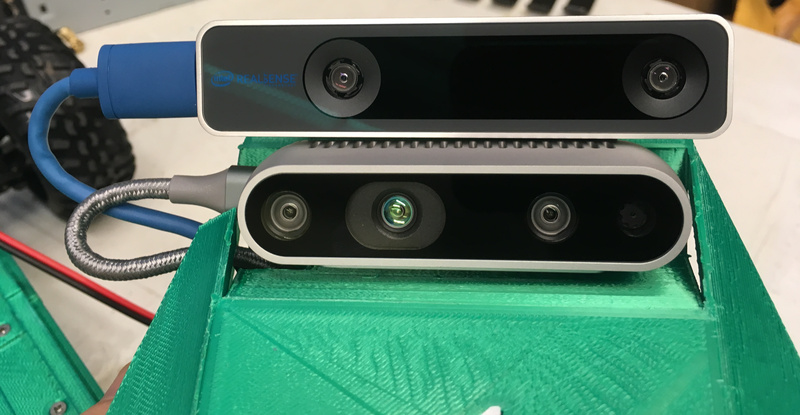
Fig. 13.5
Use five M2.5 flat head screws to mount the front cover to the race car. (Fig. 13.6)
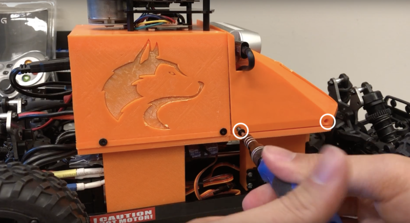
Fig. 13.6
Final Assembly
In this section, we will finish assembling the racecar.
Required Materials and Tools
- Wireless Controller
- Racecar Chassis
- 3D Printed Parts:
- 2x Racecar Cover Image
- Racecar Cover Number
- Zip Ties
- Super Glue
- Electrical Tape
Steps
Re-attach the back bumper to the chassis if not already done.
Place tape around the connections between the VESC and motor. (Fig. 14.1)
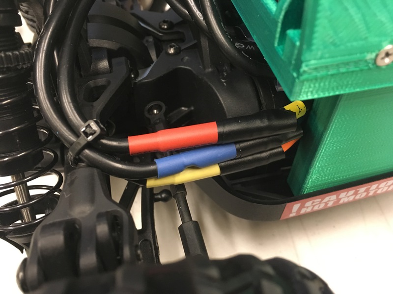
Fig. 14.1
Attach velcro to the back right side of the foundation. (Fig. 14.3)
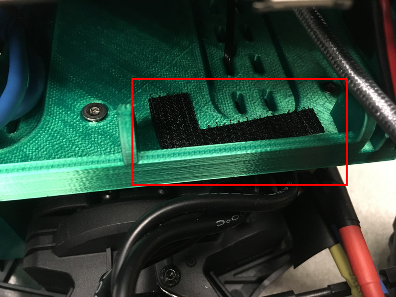
Fig. 14.2
Place velcro on the corresponding area of the battery. (Fig. 14.3)
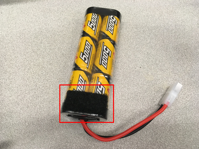
Fig. 14.3
If using the T265 Camera, use zip ties to organize the USB cable. Use zip ties as necessary to manage cables. (Fig. 14.4)
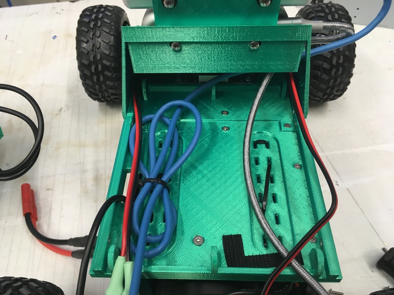
Fig. 14.4
Route the VESC’s USB cable up through the hole in the foundation near the left battery compartment. Plug it into one of the Jetson Nano’s USB ports.
Plug the YDLIDAR’s USB cable into one of the Jetson Nano’s USB ports.
Plug the USB cable(s) of any installed Realsense cameras into the Jetson Nano’s USB ports.
Make sure that the 5000 mAH battery is not plugged into the buck converter. Then plug the barrel connector into the Jetson Nano. (Fig. 14.5)
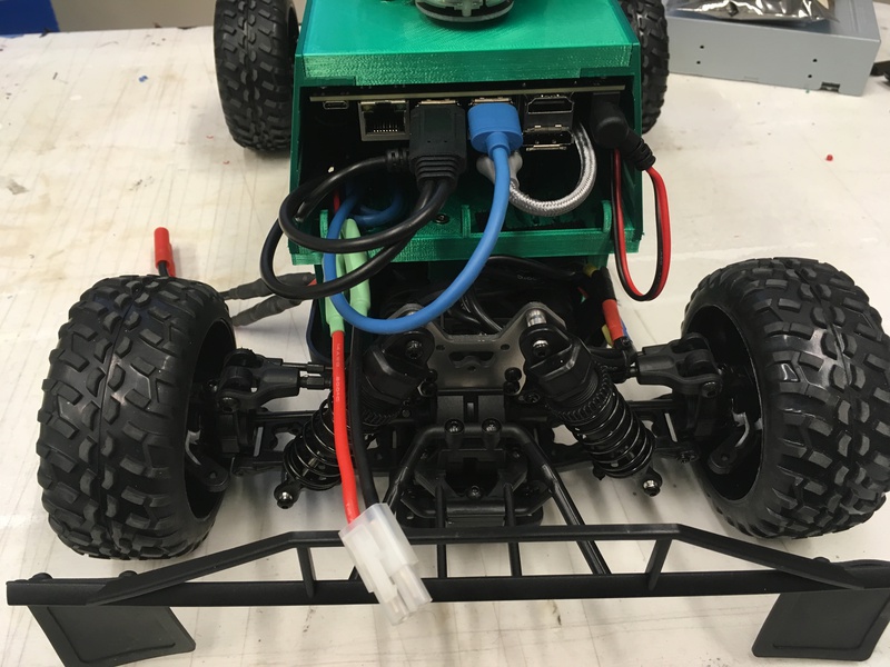
Fig. 14.5
Apply super glue to one of the insets on the outside of the back cover. Insert one of the 3D printed cover images into the inset.
Repeat the previous step for the cover image on the other side of the back cover, and for the cover number in the center of the front cover.
Congratulations, you have finished building the MuSHR Racecar! (Fig 14.6)
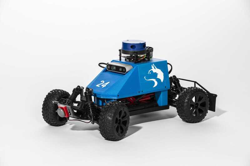
Fig. 14.6
Software Setup
In this section, we will configure the VESC firmware, pair the bluetooth controller, and setup other remaining software.
Required Materials and Tools
- Computer Monitor
- HDMI Cable
- USB Keyboard
- USB Mouse
- 3000 mAH Battery
- 5V Power Adapter or 5000 mAH battery
Steps
Attach the Jetson Nano to the computer monitor with the HDMI cable. Plug in the keyboard and mouse into its USB ports. Unplug the USB cables of the cameras if there are not enough open USB ports. Place a box underneath the chassis body such that the wheels are not touching the table/ground/surface.
Power on the Jetson Nano. You may use either a 5V power adapter directly into the Jetson Nano’s barrel connector, or use the 5000 mAH battery. Some users have had trouble booting the Jetson Nano when using the provided Jetson Nano image. In this case, instructions for installing the necessary drivers to the stock image provided by NVIDIA can be found here.
Once the Jetson Nano has booted up, login to the Ubuntu GUI under the robot username:
Username: robot
Password: prl_robotConnect to the internet by setting up a Wi-Fi connection to an existing network. First, click on the Wi-Fi symbol in the upper right of the Ubuntu GUI and choose Edit Connections. Click the plus sign to create a new connection. On the Choose a Connection Type dialog, choose Wi-Fi from the drop down menu, and then click Create…. Enter a name into the Connection Name field. Enter the name of the network to connect to in the SSID field. Under the Mode field, choose Client. Under the Device field, choose the last option (there may only be one option). Then click Save. An example connection is shown below. (Fig. 15.1)
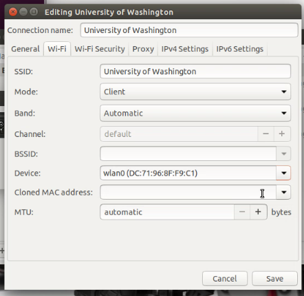
Fig. 15.1
Back in the Edit Connections dialog, double click on the Robot AP connection to begin editing the connection. Click on the General tab. Uncheck the Automatically connect to this network when it is available option. Click Save. (Fig. 15.2)
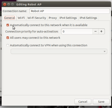
Fig. 15.2
Again click on the Wi-Fi icon in the upper right corner. Click Enable Networking. This will disable networking. Re-enable networking by again clicking on Enable Networking. The robot should now be connected to the internet through an existing Wi-Fi network. (Fig. 15.3)
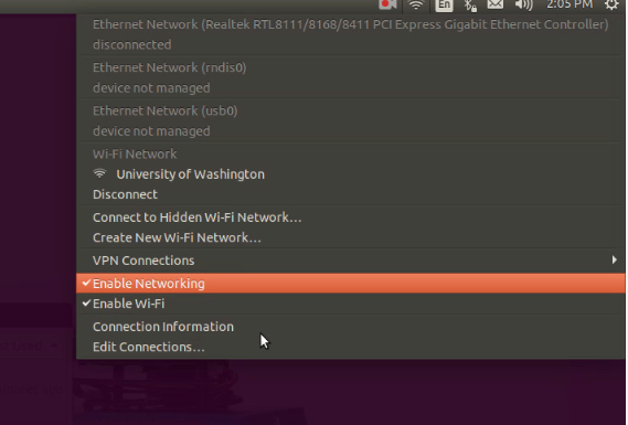
Fig. 15.3
Open a terminal and install gparted using the following command:
sudo apt-get install gpartedNext, we will use gparted to expand the SD card partition. Open the gparted program, and right click on the /dev/mmcblk0p1 partition. Choose Resize/Move. In the dialog that opens, drag the slider all the way to the right. Then click Resize. The dialog box will close. Click the green check mark, and click Apply in the resulting dialog. You should now have very little or no unallocated space. Close gparted. (Fig. 15.4)
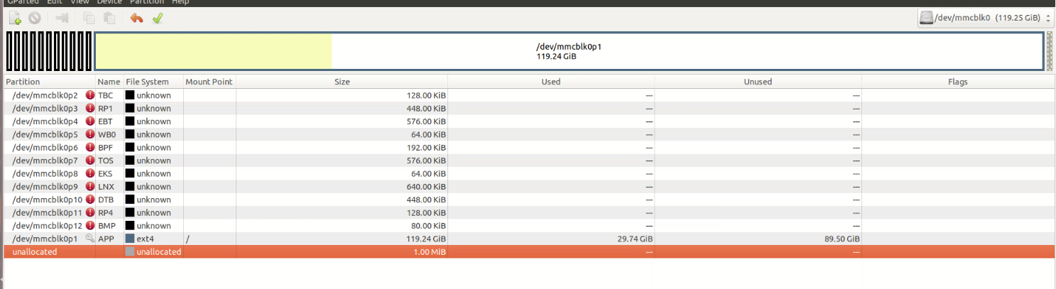
Fig. 15.4
We will now finish configuration of the VESC on the Jetson Nano. First, plug the 3000 mAH battery into the VESC. Note that you should charge the battery if not done already.
Open a terminal and use the following command to open BLDC Tool:
cd && ./bldc-tool/BLDC_ToolIn the upper right corner of the GUI, there is a dropdown box, and two buttons - one with a circular arrow and one labeled Connect. Click on the circular arrow button until the dropdown box reads VESC - ttyACM0. Look in the lower right of the GUI, where it should say Not Connected. Click on the Connect button until the text in the lower right flashes green and then reads Connected. (Fig. 15.5)
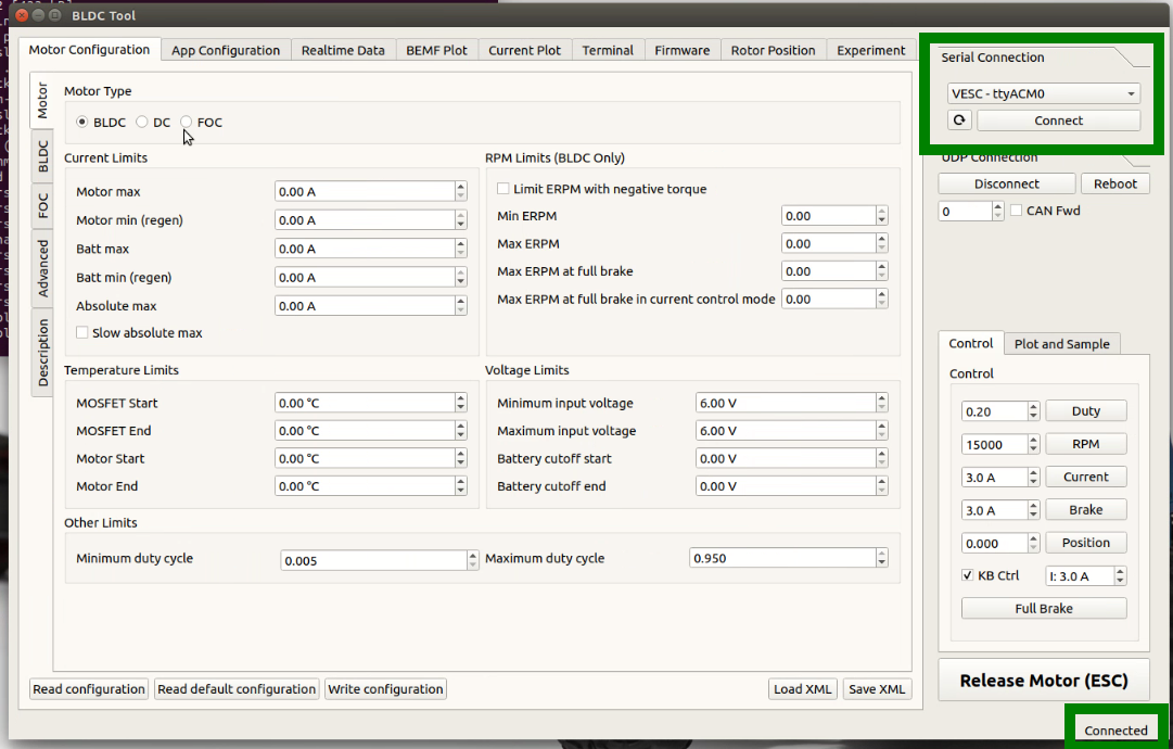
Fig. 15.5
In the lower left corner of the GUI, click the Read configuration button. Many of the fields should now be populated with non-zero values. Next, click the Load XML button. Choose the file at the path catkin_ws/src/mushr/mushr_base/vesc/vesc_configs/mushr_vesc_sensorless_config.xml. Then click Write configuration (which is to the right of the Read configuration button). Next, make sure that the robot’s wheels are suspended in air, because we are about to make the wheels move. Press (and hold) any of the arrow keys. This should cause the wheels to move. Close the BLDC Tool GUI. (Fig. 15.6)
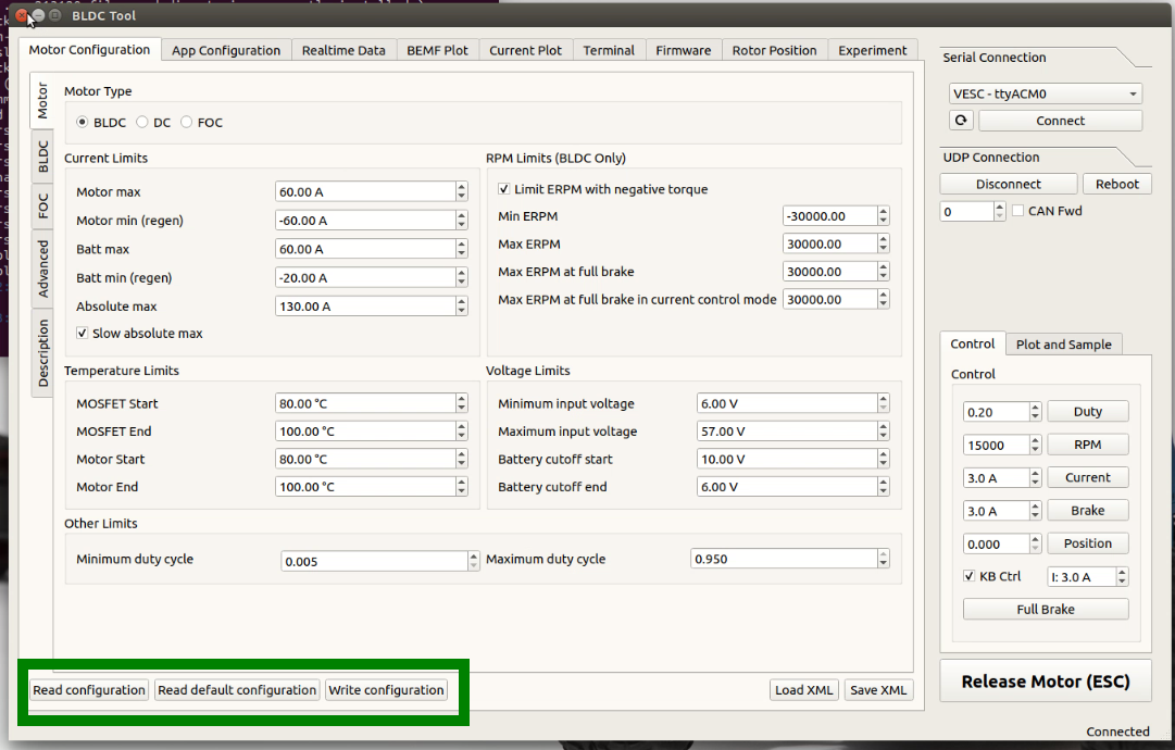
Fig. 15.6
Note the column of icons on the left-side of the Ubuntu GUI. Click on the uppermost one, and type Bluetooth. Use the search result to open the Bluetooth dialog. Turn on the PS4 controller by pressing on the Playstation button. Note that the controller must first be charged using a USB-mini cable. The LED on the front of the controller should flash. Put the controller into pairing mode by simultaneously holding down the Playstation button and the Share button. The LED on the front of the controller should continuously emit quick flashes. Next, in the Bluetooth dialog, click on the plus icon in the lower left corner. In the dialog that pops up, choose Input devices(mice,keyboards,etc.) in the Device type drop down. There should now be a single entry labelled Wireless Controller. Click it, and then click Next in the lower right corner. After the dialog reports Successfully set up new device ‘Wireless Controller’, close the Bluetooth dialog. (Fig. 15.7)
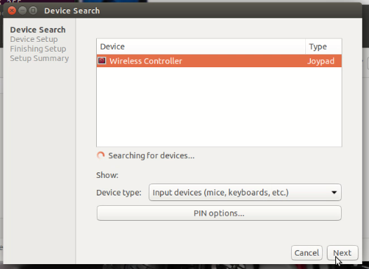
Fig. 15.7
Open the file /home/robot/catkin_ws/src/mushr/mushr_base/mushr_base/config/joy_teleop.yaml for editing. Note the hierarchal structure of this file. Under the field teleop->human_control->axis_mappings, there are two sections, each consisting of an axis, target, scale, and offset field. We will edit the section whose target field has a value of drive.steering_angle. The value of the axis field should be changed from 3 to 2. Note that this may have already been done for you as a result of future updates. Save and close the file. (Fig. 15.8)

Fig. 15.8
Open the file /home/robot/catkin_ws/src/mushr/mushr_base/vesc/vesc_main/config/racecar-uw-nano/vesc.yaml for editing. Change the speed_to_erpm_gain field to have a value of -3500, and the steering_angle_to_servo_gain field to have a value of 0.95. These parameters affect the computation of the robot’s odometry. While these values serve as a starting point, they will need to be tuned for your own car. More information about these parameters and how to tune them can be found in this tutorial. Save and close the file. (Fig. 15.9)
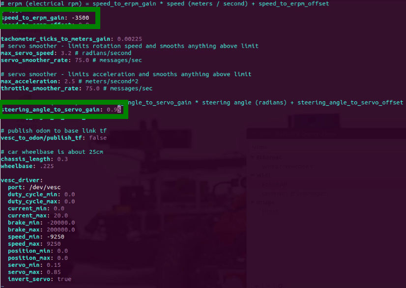
Fig. 15.9
Open the file /etc/rc.local for editing. Note that you will need to use sudo to edit it. On the line before the line that reads nvpmodel -m 0, add the following:
rs-enumerate-devices &> /dev/null
This causes the Jetson Nano to correctly recognize all of the camera devices on startup. Note that this line already may have been added for you as a result of future updates. Save and close the file. (Fig. 15.10)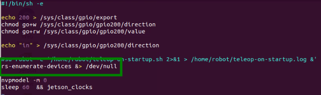
Fig. 15.10
Re-open the Network Connections by clicking on the Wi-Fi symbol in the upper right of the Ubuntu GUI and choosing Edit Connections. Highlight the connection that you created in step 4, and click the minus icon to delete it. Afterwards, Robot AP should be the only remaining connection under the Wi-Fi section. Double-click on the Robot AP connection to edit it. Click on the General tab, and re-enable the Automatically connect to this network when it available option. Click Save. Disable and re-enable networking (as described in step 6) so that the robot uses the Robot AP connection. Verify that this connection is being used by entering the ifconfig command into the terminal and checking that there is an entry containing the IP 10.42.0.1. (Fig. 15.11)
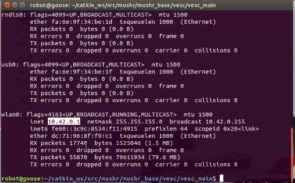
Fig. 15.11
Note that this step will cause the LIDAR to spin. Enter the following command into the terminal:
roslaunch ydlidar lidar.launchIf you get the error YDLIDAR Cannot bind to the specified serial port /dev/ydlidar, this means that the USB micro end of the LIDAR cable was plugged in backwards. Use CTRL-C to shutdown the node. Then swap the two USB micro ends of the LIDAR cable so that they are plugged into the opposite receptacles, and then try the above command again. When they are plugged in correctly, the LIDAR will begin spinning. Use CTRL-C to shutdown the node.
Shutdown the robot with the following command:
sudo shutdown -P nowOnce the robot has shutdown, unplug the monitor, keyboard and mouse. Re-insert any sensor USB cables that were removed at the beginning of this section.
You have now completely configured the MuSHR robot’s software!
Teleoperate the Robot
In this section, we will go through the minimum process required to teleoperate the MuSHR Racecar.
Steps
Ensure that both of the robot’s batteries have been charged.
Plug the VESC into the 3000 mAH NiMH battery in the chassis.
Plug the buck converter into the 5000 mAH NiMH battery in the foundation.
Wait 30 seconds for the Jetson Nano to boot up. Then connect to the robot’s network:
SSID: RobotAP
Password: prl_robotOpen a terminal and log into the robot:
$ ssh -X robot@10.42.0.1
The password is prl_robot.Execute the following command to launch the robot’s motor and sensor drivers:
$ roslaunch mushr_base teleop.launchOnce all of the robot’s nodes have been brought up, you can drive the car with the wireless controller. The LB button acts a deadman’s switch that you must hold down in order to make the car move. The left joystick controls the robot’s throttle, and the right joystick controls its steering.